To create our ALU Test Bench, first open the Design Browser window and select the ALU component from the ALU library. When you have highlighted this component, go to the File/New menu and select Create Test Bench. The Create Test Bench window, seen in Figure 1, will appear. Leave all of the settings at their defaults except for the Create Waves Test Bench which should be unselected.

Figure 1
After clicking OK, the Design Browser window will contain a new component called ALU_tb with a Block Diagram view alread created. Open ALU_tb to see a design similar to Figure 2.

Figure 2
Resize and rearrange the two blocks so that it is more readable, as in Figure 3.
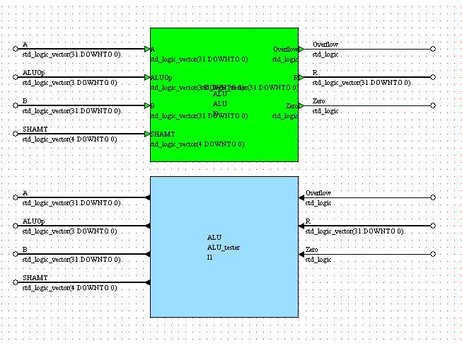
Figure 3
Notice that the signals that are output from your design component (in green) have the same name as those which are input into the sub-block called ALU_tester and vice-versa. We have not seen this before, but another feature of the Block Diagram Editor is that signals of the same name are the same signal, even if they are not visually connected together, just like in a schematics editor.
Now that we have the skeleton block diagram, we need to define what sequence of values the ALU_tester block should drive onto the inputs to the ALU component as well as what values to expect coming out of the ALU. We will do this by creating a flowchart view for the ALU_tester, which will appear as in Figure 4
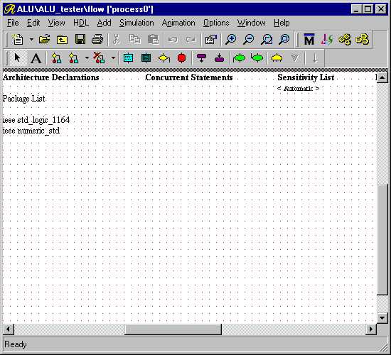
Figure 4
We begin by adding a Start Box to the diagram. Since we have many cases to test and we will not have too many opportunities to use loops to shorten the flow, we will make use of a flowchart feature called a Hierarchical Action Box to make the flowchart easier to read. A Hierachical Action Box does just what the name implies, it creates a hierarchy within the flowchart. Adding a hierarchical box allows you define a section of the flowchart in a separate window with its own Start and End boxes. When the flowchart gets to the Hierarchical Action Box, it inserts the items between Start and End in associated subview into the top level. By grouping sequences of actions into these hierarchical boxes, we can make the top level flowchart easier to read. These Hierarchical Action Boxes do not create new processes or entities, so all signals and variables which are within the scope of the parent flowchart are valid in the hierarchical box.
The first functions we wish to test are those implemented by the Logical
sub-block. Add a Hierarchical Action Box, using the button  , to the flowchart below the Start box and
label it TestLogical so that your flowchart looks like Figure 5.
, to the flowchart below the Start box and
label it TestLogical so that your flowchart looks like Figure 5.
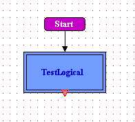
Figure 5
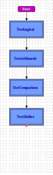
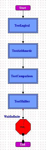
We will also be testing the functions of the Arithmetic, Comparison, and Shifter sub-blocks, so add Hierarchical Action Boxes in a chain below the TestLogical box called: TestArithmetic, TestComparison, and TestShifter. Your flowchart will now look like Figure 6.
If we were to simply place an End box after this, we would create an
infinite loop which would repeatedly run our sequence of tests. To
prevent this, we need to tell the simulator to pause. This is accomplished
by placing an unconditional wait into the flowchart. To do this,
simply place a Wait Box below the Hierarchical Action Boxes
using the Add Wait Box button,  , and
leave the text at its default: wait;.
, and
leave the text at its default: wait;.
When you place a Wait statement into your flowchart you may recieve a warning that the wait statment may not be synthesizeable. Since we only intend to use the test bench in the simulation environment, there is no intention to attempt to synthesize actual logic from it, you may safely ignore this warning.
Even though we know that we will never proceed beyond the Wait Box, the flowchart still requires an endpoint, so insert an End Box below the Wait Box. The completed top level of your flowchart should look like Figure 7.
|
|
|
|
Figure 6 |
Figure 7 |
Now we need to fill in the four Hierarchical Action Boxes, so we will start with the TestLogical box. Open the sub-chart by double clicking over the TestLogical Hierarchical Action Box. The window in Figure 8 will appear.
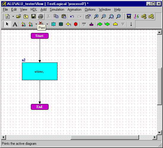
Figure 8
There is already a default flowchart containing a Start Box, a single Action Box, and an End Box. Since we will have several Action Boxes and possibly other items, we don't know yet exactly where the End Box belongs. Since we can easily add it again later, delete it.
The first step in performing a simulation test is to drive the input signals of the design unit to be tested with the first set of test vectors. Since we have already performed fairly thourough tests on the Logical sub-block as a stand-alone unit, all that we really need to confirm is that the end result, R, is correct when inputting the opcode for each different type of logical function that the ALU will perform.
By choosing the input data, A and B wisely, we create a situation where the same inputs create different outputs for each logical operation. One such set of data will be:
	A	= "01010101010101010101010101010101"
	B	= "11111111111111111111111111111111"
with the results:
	R (AND)	= "01010101010101010101010101010101"
	R (OR)	= "11111111111111111111111111111111"
	R (XOR)	= "10101010101010101010101010101010"
	R (NOR)	= "00000000000000000000000000000000"
With these inputs, we only need to force values on A and B at the start. Also, since we know that the Logical sub-block does not use the SHAMT field, we can set it to a single value at the beginning, say "01111".
To start with, then, we need to force initial values on the four signals which drive the inputs of the ALU. A, B, and SHAMT will be given the values stated above and ALUOp will be given the value "0000" to test the AND operation first. To do this, first rename the Action Box A2 as LogicalValues1. Remember, since the sub-chart is not a separate design entity, or even a separate file for that matter, you cannot use the same labels here as you use in any other part of the flowchart. When you have done this, enter the following text as the actions:
	ALUOp(3 DOWNTO 0) <= "0000";
        SHAMT(4 DOWNTO 0) <= "01111";
        A(31 DOWNTO 0) <= "01010101010101010101010101010101";
        B(31 DOWNTO 0) <= "11111111111111111111111111111111";
Your flowchart should look like Figure 9. Note that as in the truth
table, we cannot use Hexadecimal bit strings to assign values to
std_logic_vectors.
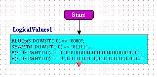
Figure 9
Now that we have assigned the input values, we need to advance the simulator so
that the result can propogate to the outputs of the ALU. To do this, we add
a Wait Box with the Add Wait Box button, .
A Wait Box places a wait statement into the process which allows for
you to either wait for a condition to occur or, in this case, to wait for a specified
amount of time. Change the label of the Wait Box to read LogicalWait1.
In the Wait Box enter the text wait for 10 ns. This will cause the test
bench process to do nothing for 10ns. The design should now look like Figure 10.
When you place a Wait statement into your flowchart you may recieve a warning that the wait statment may not be synthesizeable. Since we only intend to use the test bench in the simulation environment, there is no intention to attempt to synthesize actual logic from it, you may safely ignore this warning.
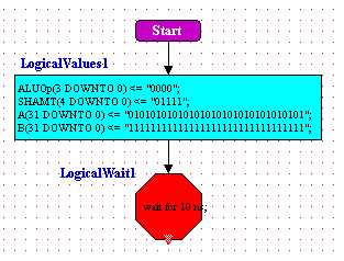
Figure 10
Now that we have allowed the simulator to advance, we will add an Action Box with an ASSERT statement to test the result. For ANDing the above values of A and B together, we expect the result R = "01010101010101010101010101010101". This assertion will output the text "Incorrect Result for AND Operation." with severity error. Add a new action box labelled LogicalAssert1 with the command:
	ASSERT (R = "01010101010101010101010101010101")
	REPORT "Incorrect Result for AND Operation."
	SEVERITY error;
The flowchart should now look like Figure 11.
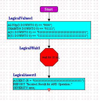
Figure 11
Since we have set up our test vectors in such a way that all four logical operations output different results, we can now test OR, XOR, and NOR by only changing the ALUOp input. Start out by selecting the two action boxes and the wait box that you just placed. With these boxes selected, press Control-C or go to the Edit menu and select Copy. Now left-click the mouse below the flowchart and press Control-V or select Paste from the Edit menu to paste copies of those boxes into the flowchart. The labels for these copies will automatically have an incremented trailing number, i.e. LogicalValues1 will be pasted as LogicalValues2.
Now, change the LogicalValues2 Action Box so that the only command is ALUOp(3 DOWNTO 0) <= "0001" to perform an or. Then change the LogicalAssert2 Action Box so that the condition is (R = "11111111111111111111111111111111") and the report text string is "Incorrect Result for OR Operation.". Your flowchart should now look like Figure 12.
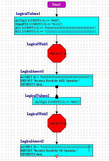
Figure 12
To finish off this Hierarchical Action Box, create two more copies of the test sequence (one LogicalValues action box, one LogicalWait action box, and one LogicalAssert action box) for the XOR and NOR cases below the first two test cases. Finally, add an End Box at the bottom.
The remaining three Hierarchical Action Boxes will be filled in similarly to the TestLogical box. The TestComparison box will be slightly longer because we have not yet thoroughly tested the Comparison sub-block. For the remaining test boxes, use what you have learned so far to implement the following test cases, with assertions on failure:
-
TestArithmetic :
A B ALUOp SHAMT R Overflow Zero "01111111111111111111111111111111" "00000000000000000000000000000001" "0100" "10000" "10000000000000000000000000000000" '1' '0' "01111111111111111111111111111111" "00000000000000000000000000000001" "0101" "10000" "10000000000000000000000000000000" '0' '0' "01111111111111111111111111111111" "00000000000000000000000000000001" "0110" "10000" "01111111111111111111111111111110" '0' '0' "01111111111111111111111111111111" "00000000000000000000000000000001" "0111" "10000" "01111111111111111111111111111110" '0' '0' "10000000000000000000000000000000" "00000000000000000000000000000001" "0100" "10000" "10000000000000000000000000000001" '0' '0' "10000000000000000000000000000000" "00000000000000000000000000000001" "0101" "10000" "10000000000000000000000000000001" '0' '0' "10000000000000000000000000000000" "00000000000000000000000000000001" "0110" "10000" "01111111111111111111111111111111" '1' '0' "10000000000000000000000000000000" "00000000000000000000000000000001" "0111" "10000" "01111111111111111111111111111111" '0' '0' "11111111111111111111111111111111" "00000000000000000000000000000001" "0110" "10000" "00000000000000000000000000000000" '0' '1' -
TestComparison :
A B ALUOp SHAMT R Overflow Zero "01111111111111111111111111111111" "00000000000000001111111111111111" "1010" "10000" "00000000000000000000000000000000" '0' '0' "01111111111111111111111111111111" "00000000000000001111111111111111" "1011" "10000" "00000000000000000000000000000000" '0' '0' "00000000000000001111111111111111" "01111111111111111111111111111111" "1010" "10000" "00000000000000000000000000000001" '0' '0' "00000000000000001111111111111111" "01111111111111111111111111111111" "1011" "10000" "00000000000000000000000000000001" '0' '0' "00000000000000001111111111111111" "11111111111111111111111111111111" "1010" "10000" "00000000000000000000000000000000" '0' '0' "00000000000000001111111111111111" "11111111111111111111111111111111" "1011" "10000" "00000000000000000000000000000001" '0' '0' "11111111111111111111111111111111" "00000000000000001111111111111111" "1010" "10000" "00000000000000000000000000000001" '0' '0' "11111111111111111111111111111111" "00000000000000001111111111111111" "1011" "10000" "00000000000000000000000000000000" '0' '0' "11111111111111111111111111111111" "10000000000000000000000000000000" "1010" "10000" "00000000000000000000000000000000" '0' '0' "11111111111111111111111111111111" "10000000000000000000000000000000" "1011" "10000" "00000000000000000000000000000000" '0' '0' "10000000000000000000000000000000" "11111111111111111111111111111111" "1010" "10000" "00000000000000000000000000000001" '0' '0' "10000000000000000000000000000000" "11111111111111111111111111111111" "1011" "10000" "00000000000000000000000000000001" '0' '0' -
TestShifter :
A B ALUOp SHAMT R Overflow Zero "11110000000000000000000000001111" "00000000000000000000000000000000" "1100" "01001" "00000000000000000001111000000000" '0' '0' "11110000000000000000000000001111" "00000000000000000000000000000000" "1110" "01001" "00000000011110000000000000000000" '0' '0' "11110000000000000000000000001111" "00000000000000000000000000000000" "1111" "01001" "11111111111110000000000000000000" '0' '0' "00000000000011111111000000000000" "00000000000000000000000000000000" "1100" "10000" "11110000000000000000000000000000" '0' '0' "00000000000011111111000000000000" "00000000000000000000000000000000" "1110" "10000" "00000000000000000000000000001111" '0' '0' "00000000000011111111000000000000" "00000000000000000000000000000000" "1111" "10000" "00000000000000000000000000001111" '0' '0'
Now that you have completed the test bench, go on to Simulating the ALU using the Test Bench.