We have now created a test bench for our ALU which will stimulate the input signals and check the validity of the outputs. The next step is to run it with our ALU design in the simulator. Before we can do this, however, we need to make sure that current versions of all of the necessary design units are generated and compiled.
To make sure that all of the sub-design units in a top level design are up-to-date, first select the top level design (in this case ALU_TB for the ALU Test Bench) in the Source frame of the Design Browser. Then, select Generate Through Components from the HDL menu. This command will descend the design tree and check to make sure that each design unit it finds has an up-to-date HDL file. If it finds a design unit with no HDL file or an HDL file that is older than the most recent design changes it will generate a new one from the source.
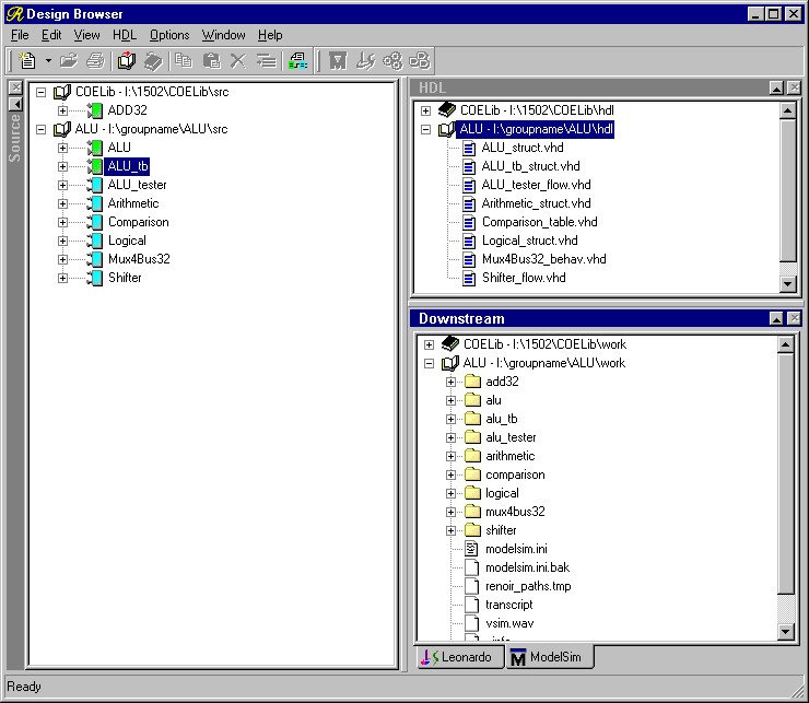
Now that we have current HDL files, we need to make sure that the compiled data for the simulator is up-to-date. In a similar fashion to the above procedure, select the ALU_TB design unit in the Source frame of the Design Browser. Now select Compile Through Components from the HDL menu. This will once again descend through the design tree. This time it will make sure that the generated HDL code is not newer than the compilation data for each sub-design unit. If it is, or the compiled data does not exist at all, then the design unit will be compiled from the HDL source.
When you have finished updating the compiled data, your Design Browser window should look something like Figure 1.
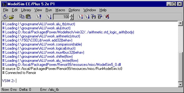
Now that we have a current compiled design, we are ready to run the simulator. Select the ALU_TB design unit once again from the Source frame and then select Run Simulator from the HDL menu. Answer OK to the defaults in the dialog box and you will see the ModelSim main window appear as in Figure 2.
We could, conceivable, just run the simulator at this point and see what happens since the stimulus and testing are all done by the Test Bench program. However, should there be an error, it would be convenient to be able to have some other information available to pinpoint it. As in previous simulations, then, open the Signals and Waves windows and add all of the top level signals to the Waves display: ALUOp, A, B, SHAMT, R, Zero, and Overflow. This will allow us to do to things: first it will let us see when we have reached the end of the tester process by displaying a the point where all of the signals stop changing; and second, it will give us a starting point in case there are any errors.
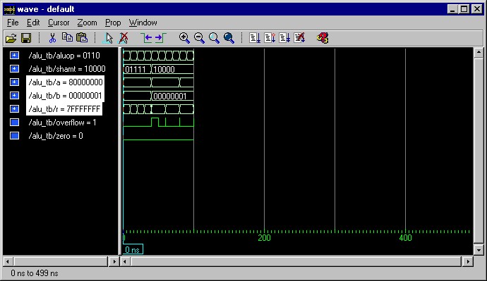
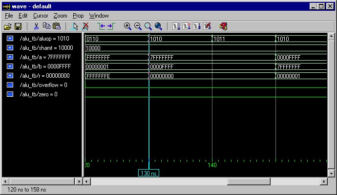
Finally, we are ready to advance the simulator. Do this by typing run in the main ModelSim window to advance the simulation by the default stepsize of 100ns. The main window will now look something like Figure 3 and the Waves window will look like Figure 4.
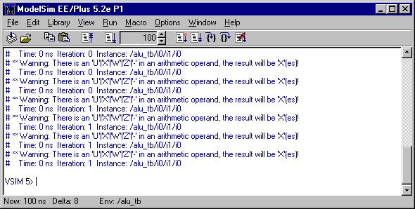
Messages from the simulator appear in blue text in the main window. So far, there are several identical warnings which occur at time=0 ns. These warnings are not serious, they are the result of there being no value on the inputs to the addition component at time zero, which is OK since we know that we have not yet stimulated those signals, so we can safely ignore these warnings.
So far things are going OK. We have made it through the first ten sets of test vectors in the test bench and have not had any report of an error. Zoom the view in the Waves window to verify for yourself that the values for the ALU outputs correspond to the accepted values.
Now enter the command run again in the main window. This time, you should see a message similar to the one in Figure 5 in the simulator window. This is the output of one of our ASSERT commands containing the severity (Error) followed by the report text. On the second line is the time at which the error occurred and the instance, which is the test bench driver where the ASSERT command is located.
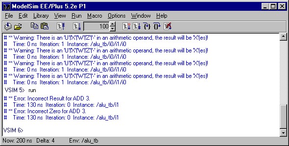
Zoom the Waves window in to examine the time in question, 130 ns, which will look like Figure 6. At 130 ns, the values are changing between test cases. The assert command takes place before the change in values, so we want to look at the waveform values to the left of 130 ns. Looking at these, we see that we have the Opcode for Signed Subtract "0110", A = -1 (FFFFFFFF) and B = 1 (00000001). We were intending to test the zero bit here, expecting the result R = 0 (00000000) and Zero = 1. However, if we look closely, to get zero we should be ADDING -1 + 1 = 0, not SUBTRACTING -1 - 1 = -2. Thus our error here is not in the design, but in the test bench itself.
Go back to the test bench flowchart and fix the mistake, setting the ALUOp for the zero test case to ADD, or "0100". Then regenerate, recompile, restart the simulator, and reconfigure the Waves window.
Now issue the run command several times until you see the signals in the waves window remain static for 100 ns or more. If there are any more error reports which appear in the main window, then you have an error in your design which you will need to track down. Otherwise, you have completed the testing of your ALU.