Unit 1b
Introduction to ModelSim tool:
Simulating the Logical Sub-Block
The ModelSim Simulator
Now that we have created a design unit which has a clearly defined behavior,
we need to verify that we have correctly specified that behavior in the
VHDL code. We will do this using Packaged Power's simulation tool,
ModelSim.
ModelSim is a very powerful and versatile HDL simulation tool
which has been tightly integrated with Renoir. As a result, there
are several methods by which we could go about verifying our design ranging
from loading the bare design unit into the simulator and watching the outputs
as we force the input signals into different states to creating a VHDL
Test Bench which will automate this process for us. For our introduction
to ModelSim, we will be using the first approach to get a feel for
some of what the simulator can do.
The ModelSim simulator cannot directly load and simulate your
Renoir design unit source files. In order to prepare a design for
simulation, two steps must be taken: generation and compilation.
You should have already generated the HDL code for the Logical
sub-block design unit. Verify this by looking in the upper right hand frame
of the Design Browser, expanding the tree for the ALU library
and making sure that there is a file there called Logical_struct.vhd.
If this file is not there, follow the procedure you have already learned
to generate it.
Before we can compile the design unit, we must extend the library mapping
to specify a directory for "Downstream Data", in this case the ModelSim
simulator. You can do this by opening the Library Mappings window
from the Options menu at the top of the Design Manager. In
the Library Mapping window, select the ALU library and press
Modify. This will bring up the Modify Library Mapping window.
The bottom option is for DOWNSTREAM - Compiled Data. The Mentor
Graphics convention is to place simulation compiled data in a subdirectory
of the library directory called work. So, make sure that the list
box directly below the work Downstream is set to ModelSim, ModelSim
4.7 PE and then type I:\groupname\ALU\work in the field
for the location.
Once the VHDL for the Logical sub-block has been generated, it
needs to be compiled into a ModelSim simulation file. This can be
done from the Design Browser window by highlighting the Logical
design unit and selecting the Compile option from the HDL
menu which can be accessed either on the top menu bar or by right-clicking
over the design unit in the source frame. The log window should tell you
that the compile has completed and there should now be a folder labelled
Logical in the Downstream frame under the ALU library tree.
If there is a problem, check the design unit block diagram for errors and
call the TA or instructor.
Once the design has been compiled, you can start the simulator. Before
doing so, open the Logical block diagram. This is not necessary,
but allow data from the simulator to be annotated to the design source
to ease debugging. To open the simulator and load the Logical design
unit, select the design in the Source frame of the Design Browser
and then select the Start Simulator option from the HDL menu.
This will bring up the options window seen in Figure 1. Leave all of the
default options as they are and click OK.
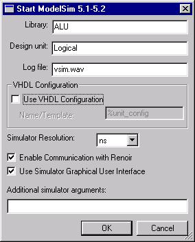
Figure 1
After a few seconds, the ModelSim main window pictured in Figure
2a will appear. You will also notice that the bottom of the Renoir
design window with the Logical sub-block diagram has a new simulation
toolbar pictured in Figure 2b.

Figure 2a
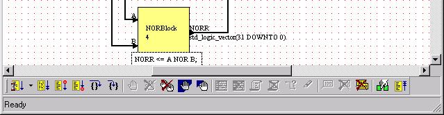
Figure 2b
In addition to the ModelSim main window, where all text commands
to the simulator are entered, there are several other graphical interface
windows available. In this section of the tutorial we will be using the
Signals and Waves windows.
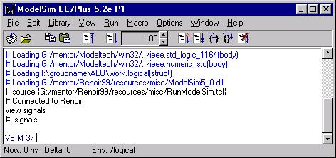
To display the Signals window, go to the View menu in
the main ModelSim window and select Signals from the list.
Notice that in the main window (Figure 3a), the command view signals
was automatically issued and this resulted in the appearance of the signals
window on the right as seen in Figure 3b.
You will find that most current digital simulators consist of graphical
shells which issue text commands to the actual simulator. This is a remnant
of the fact that until recently most serious digital simulation was done
on high-end UNIX workstations where a text interface is the norm.
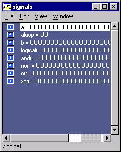
Looking at the Signals window, you can see that all of the ports
and internal signals for the Logical sub-block are present. Since
the simulator has not yet un forward in time, they are all currently in
an undefined state.
|
|
Figure 3a
|
Figure 3b
|
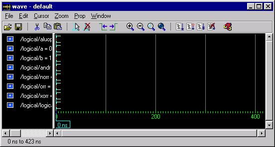
Next open the Waves window from the View menu. The window
in Figure 4 will appear. This is the waveform viewer for ModelSim.
By default, it appears without any signals in the viewing area, they must
be added by hand.
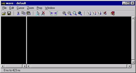
Figure 4
Now that we have the Signals and Waves windows open, we will
start adding signals to the waveform viewer. There are several different
ways to do this. We will do it by dragging them from the Signals
window and dropping them into the left hand frame of the Waves window.
Begin by selecting the ALUOp signal in the Signals window by
left-clicking over it. Once you have selected it, left-click again and
this time hold the mouse button down. While the mouse button remains depressed,
drag the pointer over to the Waves window and release. The Waves
window should now look like Figure 5.
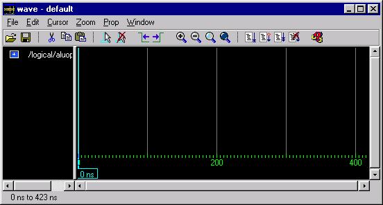
Figure 5
Now drag the A and B signals respectively into the Waves
window so that it looks like Figure 6.
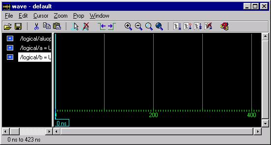
Figure 6
We can also drag multiple signals at once. Left-click on the XORR
signal in the Signals window to select it, but this time hold the
mouse button down and drag the pointer up so that the bottom five signals
are highlighted before you release. Now left-click and hold again and drag
this group of signals onto the Waves window, which should now resemble
Figure 7.
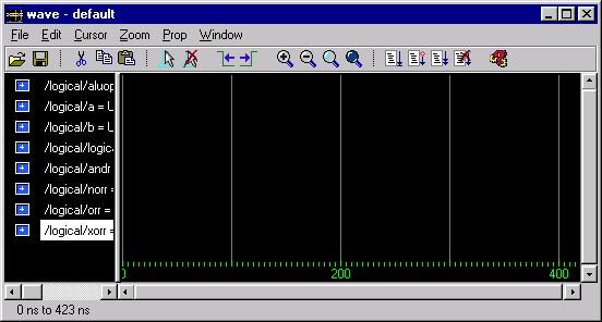
Figure 7
Finally, within the Waves window we can rearrange the display order
to our liking. It is often convenient to place the output or outputs of
the design unit at the bottom of the waveform display. Currently, however,
the LogicalR signal is sitting in the middle of the display. Select
this signal in the left-hand frame of the Waves window by left-clicking.
Now left-click and hold and drag it down to the bottom of the list. Your
waveform display should now look something like Figure 8.

Figure 8
Now that we have our display set up to our liking, lets look at how we
can make this simulation do something. The most direct way to do this is
to stimulate the input signals by forcing them to particular values. Remember,
forcing a signal to a value does not actually take effect until you advance
the simulator time.
The command in ModelSim to stimulate a signal is called force.
For our first timestep, we wish to set the ALUOp to "00", so we type force
ALUOp 00 at the VSIM prompt and hit return. The main window
will now look like Figure 9. Constant strings of bits can simply be represented
by a sequence of ones and zeros.

Figure 9
For the inputs, A and B, we also wish to assign values. However,
for signals with so many bits, it is tedious to type out the constant assignment
values bit by bit. Instead, it is possible to represent constant values
in other bases like hexadecimal or decimal which will be converted to actual
bit strings by the simulator. There are two equivalent syntaxes to do this.
One is to type a decimal number representing the base, followed by the
# sign, followed by the value in the appropriate base. The other is to
use the VHDL standard method of the base identifier (hexadecimal is X)
followed by the value in double-quotes.
We will be assigning A to a value of all zeros and B to
a value of all ones. In hexadecimal assignment, this would be done by typing:
      force A 16#00000000
      force B X"FFFFFFFF"
into the main window as seen in Figure 10.
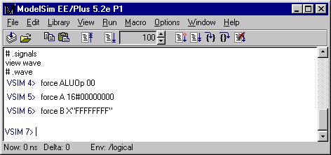
Figure 10
Finally, we need to step the simulator forward in time. Since we do not
have any timing delay information in our design, leading to all transitions
occurring instantaneously, the amount of time we step by means little,
so for starters we will move forward 10ns. We run the simulator for a specified
amount of time by typing run xxx where xxx is a time in nanoseconds.
So type run 10 at the prompt as seen in Figure 11a.
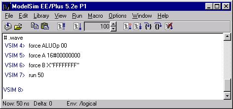
Figure 11a
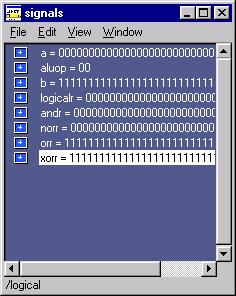
Now that we have moved forward with stimulus on the inputs, there should
be well defined values at the outputs and the waveform window should hold
history of the specified signals for zero to ten nanoseconds. Your Signals
and Waves windows should look like Figure 11b and 11c respectively.
|
|
Figure 11b
|
Figure 11c
|
Unfortunately, in the default configuration, the data in the Waves
window is impossible to read. This can be fixed in several ways. First
resize the window, if you haven't already done so, so that it takes up
most of the width of the screen.
Next, highlight all seven of the 32 bit signals and go to the Prop
menu on the Waves window. About midway down there will be a listing
of different radix values: select hexadecimal to change the display radix
to hex format.
Now position the pointer over the divider between the two viewing frames.
Left-click over it and drag to the right until all of the signal values
in the left frame are visible. The left frame contains the name of the
signals and the value of each signal at the point in the waveform window
that the cursor is located.
Finally, click the right-most magnifying glass on the toolbar (the one
with the dark-blue center) to maximally zoom in on the displayed waveform.
Your Waves window should now look like Figure 12.
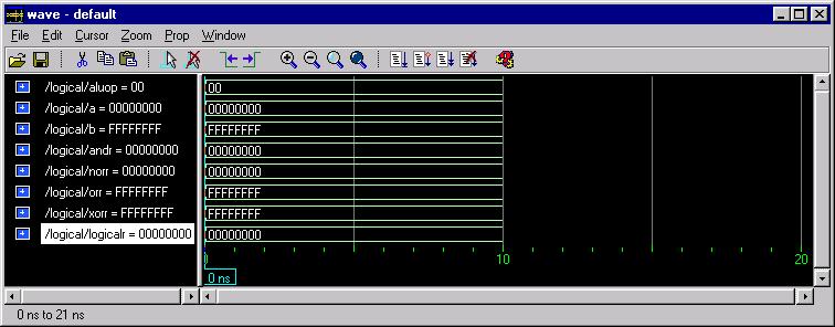
Figure 12
Now to show a transition on the output, lets change up the values of the
inputs. Set ALUOp to "10", A to X"00000000", and B
to X"FEDCBA98" and then run the simulator for 20ns.
The waveform display should now show the update values for ALUOp and
B transitioning at 10ns as well as new values for NORR = X"01234567"; ORR=
X"FEDCBA98"; XORR= X"FEDCBA98"; and LogicalR = X"FEDCBA98" also transitioning
at 10ns. Check to make sure that your waveform window looks like Figure
13: if not then you have an error in your design.
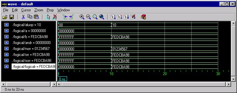
Figure 13
In addition to viewing the simulator output in the various ModelSim
windows, data is annotated to the original Renoir design. Go to
your opened Logical block diagram. If you have no signals selected,
at the bottom of the window on the simulation toolbar, there will be a
grayed out button labelled Add Probe,  .
By selecting a signal or bus in the design, this button will change color
and allow you to activate the tool:
.
By selecting a signal or bus in the design, this button will change color
and allow you to activate the tool:  .
Activate this tool, move the mouse pointer over the ALUOp bus, and
left-click. This will add a probe to the net, meaning that the current
simulator value of that signal will be displayed in a red box near the
net. The design area should now look like Figure 14.
.
Activate this tool, move the mouse pointer over the ALUOp bus, and
left-click. This will add a probe to the net, meaning that the current
simulator value of that signal will be displayed in a red box near the
net. The design area should now look like Figure 14.
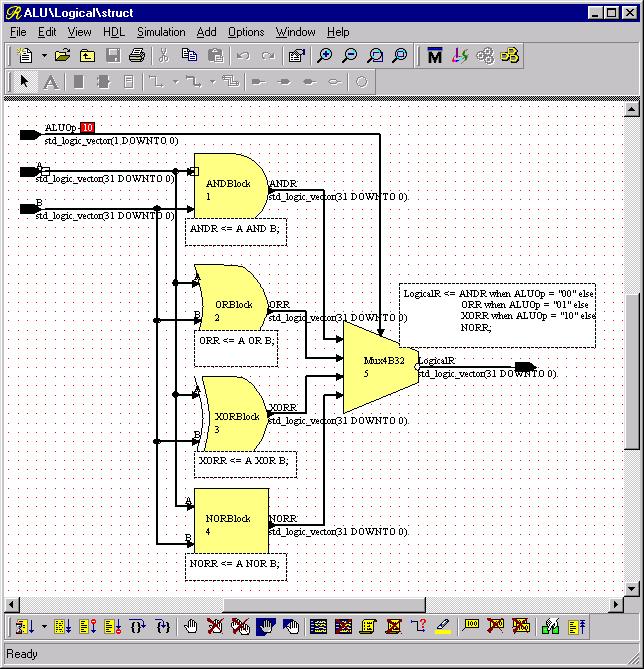
Figure 14
Now add probes to all of the signals on the diagram so that it looks like
Figure 15.
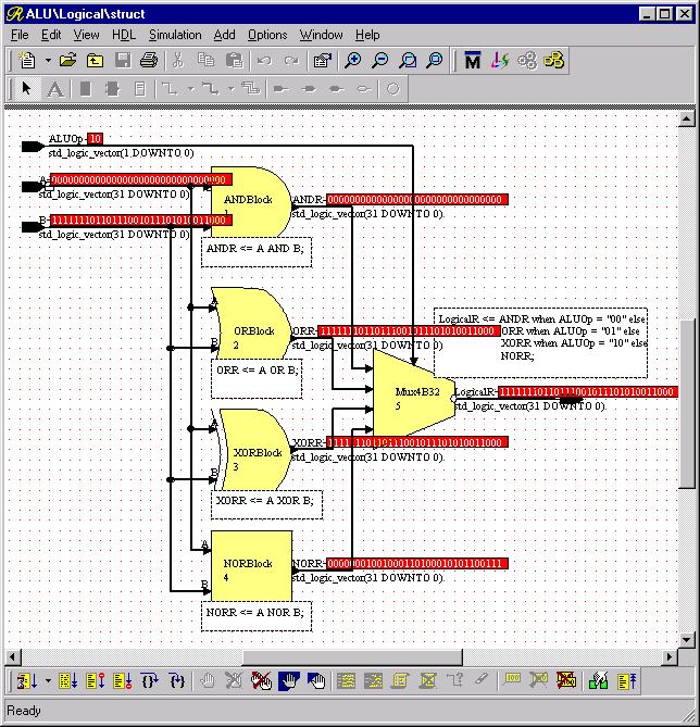
Figure 15
Now we have seen several ways to look at the values in the simulator. However,
it is still a tedious process to individually type all of the stimulus
commands for a complete design test. To this end, we can use something
called a Macro File. A macro file is simply a text file which can
be created by a program such as notepad containing a sequence of ModelSim
commands. In ModelSim these are usually saved with the extension
.do since they are also known as do files and are executed
via the do command.
To test the Logical sub-block a little bit more fully, I have
created a small sequence of simulator commands and commented it. Enter
this sequence of commands in a Notepad or other text editor and save it
as I:\groupname\ALU\LogicalTest.do. (You may leave out the
comments or cut and paste)
-- First set A and B to zero and the ALUOp to NOR (11).
-- Check that NORR and LogicalR are both "FFFFFFFF" and
-- that ANDR, ORR, and XORR are all "00000000".  This
-- will verify one test case for each individual logic
-- operation and will verify that the "11" select of the
-- multiplexor is working.

force ALUOp 11
force A X"00000000"
force B X"00000000"
run 10

-- Now leave A as zero, set B to "FFFF0000" and set the
-- ALUOp to 00.  Check that ANDR and LogicalR are
-- both "00000000".  Since ANDR is the only intermediate
-- result that should be zero, if LogicalR is also
-- zero, then the multiplexor should be working for "00"
-- on the select.  ORR and XORR should be "FFFF0000" and
-- NORR should be "0000FFFF".

force ALUOP 00
force A X"00000000"
force B X"FFFF0000"
run 10

-- Now we will set A to "FFFFFFFF" and B to "F0F0F0F0".
-- This will give a unique answer for ORR of "FFFFFFFF"
-- so we will set ALUOp to "01".  Check that ORR and
-- LogicalR are "FFFFFFFF".  ANDR should be "F0F0F0F0",
-- NORR should be "00000000" and XORR should be "0F0F0F0F".

force ALUOp 01
force A X"FFFFFFFF"
force B X"F0F0F0F0"
run 10

-- Since there is a unique value for the only ALUOp which
-- we haven't tested on the multiplexor with the
-- current values of A and B, we can leave them alone
-- and set the ALUOp to XOR or "10".  This time all that
-- we need to check is that LogicalR is now equal to
-- the value of XORR, or "0F0F0F0F".

force ALUOp 10
run 10
Once you have entered and saved this text we are ready to run the macro
file. First, however, we will want to reset the simulator so that we are
starting from time zero. This is done by entering restart at the
main ModelSim window prompt. Now run the command file by entering
do I:/groupname/ALU/LogicalTest.do at the prompt in the main
ModelSim window. Be careful to use forward slashes instead of normal
NT backslashes in the directory name and make sure that the file does not
have a hidden .txt extension.
Confirm that your design is functioning properly by checking the actual
values in the Waves window with the expected results. The final
output should look something like Figure 16.
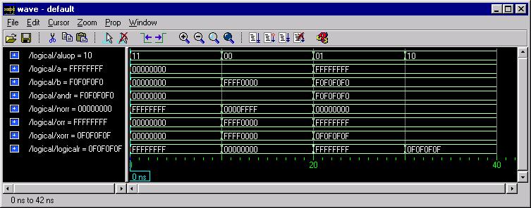
Figure 16
Now that you have verified the functionality of your first design unit,
we can go on to create the next one in Creating
the Shifter.