IC Builder User Manual
This Symbolic IC_Builder Version 2.0 has the following features:
- Don't need to specify the message ID and action ID any more, i.e. directly
use the symbolic name.
- The ic.dat file will be automatically generated.
- Simple project manager manages all the ICs in the project.
- IC_Builder knows whether the current file has been changed or not.
1 Define a Project
1.1 Create a Project Directory as Your Work Space
Create a directory in the disk, which will contain all the project files later.
For example, c:\icb\hw4\.
1.2 Specify Project Files
In the IC Builder menu bar, find the 'simulation' menu.
Select the 'options' menu item.
This will bring up a dialog which ask you to specify the executable
file of the application and the external input message file if necessary.
Please be sure to specify the complete path of the project directory so that
any file generated by IC_Builder will be put in this directory.
For example,if your executable file will be wag.exe, then at the
first line input the following:
c:\icb\hw4\wag.exe
The second line can be something like:
c:\icb\hw4\mag.in
which means the external input message file is msg.in.
1.3 Specify IC Types used in the Project
Also in the 'simulation' menu, select the 'project' item to define the
project files in the project. You could add or remove the files from the project.
please use the name of IC file, don't use the .in name. For example,
if your project contains three ics: WAG, BBC, LBC
then the project files could be:
WAG.gra BBC.gra, LBC.gra
2 Define IC Types
2.1 Draw a State
Click (press left mouse button) the icon in the tool bar, then point the
cursor at the desired position, press left button. The state will be numbered
automatically.
2.2 Delete a State
Click (press left mouse button) the Delete_State icon in the tool bar,
then move the cursor within the state which you want to delete, press left
button.
2.3 Move a State
Currently, there is no way to move a state to a different position, you
have to delete and draw a new one to achieve the reposition of the state.
2.4 Change the ID number of the State
Click (press left mouse button) the Change_ID icon in the tool bar, then
click on the state you want to change. A dialog will appear to let you
enter the new number of the state.
2.5 Draw a Transition
There are two ways to draw a transition between states. One way is to draw
a straight line, the other is to draw a line with turning points. Either
way you should first click the icon, then move the cursor to the transition
start position on one state, then click. Then you can move the cursor to
the next position, click, and so on (if you are not using the draw straight
line icon ). Finally you double click the left button to select the end
position of the transition. Be aware that the start and end positions should
always be on the edge of the state. The start position is marked as a small
green rectangle, and the end position is marked as a red rectangle.
2.6 Delete a Transition
Select the Delete_Transition icon in the tool bar, move the cursor to the
start position of the transition, then click the left button.
2.7 Define a Transition
Click the Define_Transition icon in the tool bar,
then move the cursor to the start position of one transition, click the
left button. A dialog like above will appear on the screen. This dialog
lets you to add as many transitions between two same states as you want.
Click the two buttons on the right of the dialog to further define the
input or output message of one transition between the two states.
2.7.1 Define Input Message
Input Message Specification Dialog
As you click the Define Input Message button, the Input Message Specification
dialog will prompt, as the figure below. There are two columns in the dialog,
the left one is used to specify input message's name, parameters. The right
column is used to define the predicate for input messages. You can add
or delete the input message and predicate. Please refere to Section three
for the format of the input field "Parameters".
Notice: Message name is case insensitive.
2.7.2 Define Output Message
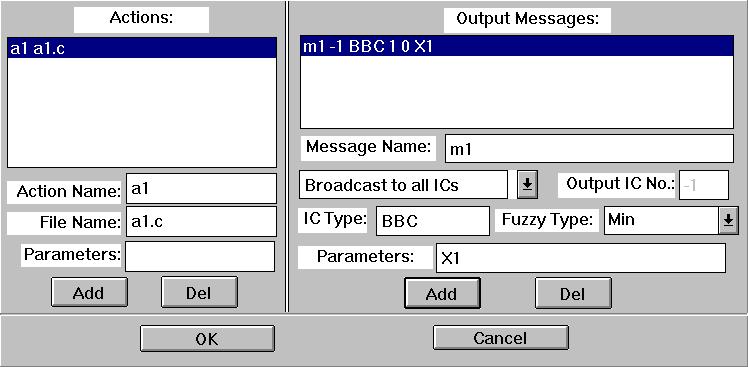
Output Message Specification
There are two columns in this dialog, the
left one is used to define the action for the transition. Two fields are
needed for each action, the action name (case insensitive) and the name
of the file which contains the action. The right column defines the output
messages in the transition. Please refere to Section three
for the format of the input field "Parameters" in the action and output message.
There are six options for the field "Output IC NO.".
- "Specify an Existing IC ID"
- For this option, the user have to specify a positive integer as the IC ID.
- "Send to a New IC"
- For this option, the corresponding output message will be post to an IC
which will be activated when this message comes.
Please notice you must specify the IC type in the field "IC type".
- "Broadcast to All ICs"
- For this option, this message will be broadcast to all ICs.
If the IC type in the field "IC type" is specified, the message will
be broadcast to all ICs of the specified type. If not, the message will
broadcast to all ICs which can receive the message.
- "Contended by All ICs"
- For this option, this message will be contended by all ICs.
If the IC type in the field "IC type" is specified, the message will
be contended by all ICs of the specified type. If not, the message will
contended by all ICs which can receive the message.
- "Broadcast to Selected ICs"
- For this option, this message will be broadcast to the selected ICs.
The user has to program a function to compute the selected ICs.
If the function needs to know the IC type, the user has to the IC type
in the field "IC type".
- "Contended by Selected ICs"
- For this option, this message will be contended by the selected ICs.
The user has to program a function to compute the selected ICs.
If the function needs to know the IC type, the user has to the IC type
in the field "IC type".
-
2.8 Export the IC diagram
The IC diagrams definition need to be transformed to so called .in file
when it is used as the input of the IC_Manager. Click the Export icon in
the tool bar to export the diagram as a .in file. The export operation
will create all the .in files in the project plus a ic.dat file for the
input of IC compiler.
3 Format of the parameter in the Message Definition Dialog
<para_list> ::= <para_list>'|'<item>
<para_list> ::= <item>
<item> ::= <const> | <var> | <func>
<const> ::= I<integer> | F<float> | S<string>
<var> ::= X<digit> | Y<digit> | Z<digit>
<func> ::= G<digit>'('<func_para_list>')' | H<digit>'('<func_para_list>')'
<func_para_list> ::= <f_para_list> | NULL
<f_para_list> ::= <f_para_list>','<item>
<f_para_list> ::= <item>
<digit> ::= '0'..'9'
For example,
X1|Y1|G7(X2, Y2) in the field parameters means that
X1 and Y1 are variable parameters and G7 is a function parameter which
has two variable parameters X2 and Y2.
I25|F1.2|Sfire means that there are three constant parameters:
an integer 25, a floating point 1.2 and a string "fire".
4 Sample .in File
0          // current state
0          // next state
1          // 1 input message(s)
10:0,Y1|Y0 // message start_prefetch with 2 parameters
0          // no. predicate
0          // 0 output ic(s)
0          // 0 output message(s)
3          // 3 action(s)
11         // action "issue_proc"
12         // action "set_pid"
14,Y1|Shelp|H0(Y0) // action "compute_schedule" with 3 parameters
0          // current state
0          // next state
1          // 1 input message(s)
11:0       // message "end_prefetch"
0          // no. predicate
0          // 0 output ic(s)
0          // 0 output message(s)
1          // 1 action(s)
15         // action "set_pid_null"
0          // current state
-1         // next state
1          // 1 input message(s)
12:0       // message "kill_prefetch"
0          // no. predicate
0          // 0 output ic(s)
0          // 0 output message(s)
1          // 1 action(s)
13         // action "kill_proc"