A Testbed for Personal HealthCare Slow Intelligence System
In what follows, we describe
a Testbed for Personal HealthCare Slow Intelligence System.
This testbed can be used for component-based SIS development.
System Description
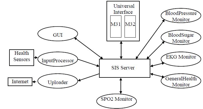
The Personal HealthCare Slow Intelligence System PHSIS
consists of the following:
(1) Universal Interface: The Universial Interface is for testing the system.
The user can enter a message on the left panel, and
observe an output message on the right panel.
In fact, any message sent from one component to
another component will be displyed on the right panel.
The actual message sent has the following
format: Name$$$Value$$$... Name$$$Value$$$,
i.e., name and value pairs with three dollar signs serving
as delimiters.
(2) SIS server: The SIS server processes messages.
The special messages Create, Kill and Activate will
enalbe the SIS server to create, kill and activate
a component. Other messages will be routed to
the receipient components by the SIS server.
(3) Input Processor: The Input Processor is a predesigned
componet which inputs data stream generated by the
Health Sensors and outputs data streams specific
for the various vital signals such as blood pressure,
blood sugar, Pulse Oximeter Oxygen Saturation (SPO2), EKG and so on.
(4) Uploader: The Uploader is a predesigned component
which inputs data streams and uploads them via the
Internet to a shared database so that
patients, physicians and other authorized personnel
can access patient information.
(5) Other Components: These components include
the GUI and various monitors including:
BloodPressure Monitor, BloodSugar Monitor,
EKG Monitor, SPO2 Monitor, GeneralHealth Monitor, and so on.
These are the components to be developed by class projects.
The above diagram can be redrawn as an UML
deployment diagram as follows.
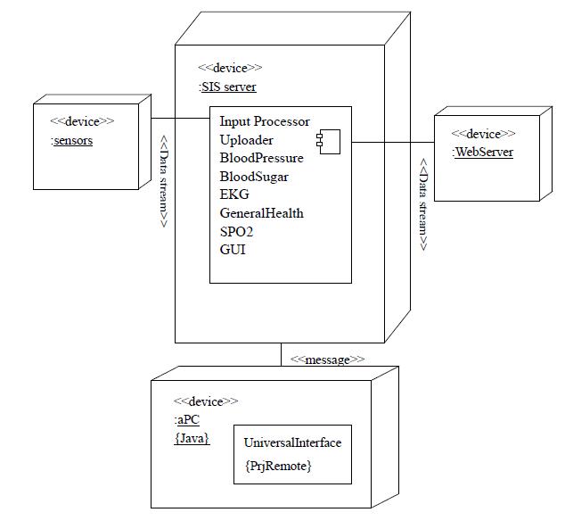
The Universal Interface, the SIS server, the InputProcessor
and the Uploader constitute the Component Infrastructure
(see Chapter 15 on component infrastructure)
. The other components are built with
respect to this Component Infrastructure.
System Installation
The Lightweight SIS testbed consisting of the Universal Interface and SIS Server
can be downloaded from
SISServer.zip.
Once downloaded, just follow the
Setup Procedure
to install.
The HealthCare SIS testbed can be downloaded from
SISv2c.zip.
Follow the Complete Setup Procedure to install the healthcare SIS testbed.
Finally the Developer's SIS testbed
can be downloaded from SISv3n5r.zip
(available upon request to students working on approved class projects).
The setup procedure and user manuals are in the Documents folder of the downloaded testbed.
You are now ready to develop and test
your plug-in components.
Preliminary Condition
UniversalInterface, SISserver and HealthSensors pre-exist or have already been instantiated/activated.
GUI, InputProcessor, BloodPressure Monitor and Uploader will be instantiated/activated.
(In case some of these components are not available, it
is still OK. You can use the UniversalInterface to
simulate messages from these components. Messages
to these components will be ignored by the SIS Server,
but still displayed on the right panel of the
UniversalInterface. For the class projects,
for example, you can simulate messages from InputProcessor.
Therefore, you don't need to have access to the HealthSensors
to develop and test your plug-in components.)
UniversalInterface sends Msg 20 (BBB create) to SISserver to instantiate/activate GUI
UniversalInterface sends Msg 20 (BBB create) to SISserver to instantiate/activate InputProcessor
UniversalInterface sends Msg 21 (ABB create) to SISserver to instantiate/activate BloodPressure Monitor
UniversalInterface sends Msg 21 (ABB create) to SISserver to instantiate/activate SPO2 Monitor
UniversalInterface sends Msg 21 (ABB create) to SISserver to instantiate/activate EKG Monitor
UniversalInterface sends Msg 20 (BBB create) to SISserver to instantiate/activate Uploader
A Scenario
GUI interacts with the user and sends Msg 45 (user profile)
containing UserName, Age, Sex, Weight, Height and medical conditions,
to Uploader and all Monitors.
HealthSensors sends Msg 30 (sensor data input) to InputProcessor, which parses the data and extracts vital signals. (InputProcessor accepts Msg 30 sensor data input and produces Msg 31, 33 or 35. However Msg 30 may not be a formatted message)
InputProcessor sends Msg 31 (blood pressure reading) to BloodPressure Monitor, which checks for abnormality. There could be a knowledge base, but initially we just check if high blood pressure reading is over 130 to generate an alert. (BloodPressure Monitor accepts Msg 45 and Msg 31 and produces Msg 32)
BloodPressure Monitor sends Msg 32 (blood pressure alert) to GUI, which displays the vital signals. (GUI accepts Msg 32, 34, 36, 38 and produces Msg 20, 21)
BloodPressure Monitor sends Msg 32 (blood pressure alert) to Uploader,
which uploads patient's UserName and medical conditions to remote database. (Uploader accepts Msg 32 and uploads it. The uploading may not be a formatted message)
(There are other messages and other components for heart
rate, SPO2 level, EKG signals for irregular heart beats, etc.
But it is the same scenario, only more complicated.
The GUI may also need to display the combined vitals.)
Design Considerations
A monitor component and the associated knowledge
base component can be considered as one
coarse grained business component.
The refined monitor component and the associated knowledge
base component are the fine grained components.
(See Chapter 16 on business components.)
A component is brought to life by the "Create
Component" message (Msg ID 20, or 21 if there is a
knowledge base).
When a component first comes to life, it should send
a "Connect to Server" message (Msg ID 23) to the SISserver.
SISserver will return an Ack message (Msg ID 26) to
the said component. The "Activate Component"
message (Msg ID 24) and "Deactivate Component" message
(Msg ID 25) will activate/deactivate the said
component. Finally, the "Kill Component" message
(Msg ID 22) will destroy it.
Component Specification
We need to specify at least the input messages,
output messages, the variables (attributes)
and the methods for the components.
Therefore the class diagrams should be prepared.
For a complete specification we can use the following UML diagrams:
The use-case diagram specifies the major
use-cases (or components).
The sequence diagram describes the interactions
among the classes and actors based upon messages.
The state diagram describes the state transitions
for the major component(s).
Special attention should be paid to the interface.
For more details about interface see Chapter 17 on Components and Connectors.